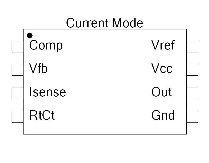
SingleEndedIC - Logic Delay

Connection Diagram:
| A | 
| AA | |||||
| B | BB | ||||||
| C | CC | ||||||
| D | DD | ||||||
| Connections(58) | Position | Remark |
| DD | Right | |
| D | Left | |
| CC | Right | |
| C | Left | |
| BB | Right | |
| B | Left | |
| AA | Right | |
| A | Left |
| Parameters(5) | Default | Remark |
| UnityBandWidth[Hz] | 1e6 | Band width of the Error Amplifier. At this frequency the gain equals 1. Specify in [Hz] |
| DCgain[.] | 30000 | DC gain of the open loop Error Amplifier. (Around 100dB for a current mode controller) |
| ImaxEAoutputCurrent | 500uA | Maximum output current the Error Amplifier can deliver (ususlly around a couple of mA) [Ampere] |
| UVLO_ON[V] | 8.5 | |
| UVLO_OFF[V] | 7.9 |
| Function | Delay block for delaying a gate control signal. | |
| Status | Standard | |
| Select from | Components\Library\PowerConverters\SMPS\Control\CurrentMode | |
See also
DualEnded, Oscillator, SingleEndedMax50IC, SingleEndedSynIC, TimerGate, TimerGateOscillator,


