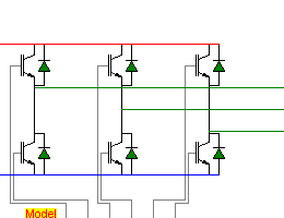
Inverter_IGBT - 3 phase IGBT inverter

Connection Diagram:
| DC | 
| ||||||||||||
| U | |||||||||||||
| V | |||||||||||||
| W | |||||||||||||
| GND | |||||||||||||
| AM | G1A | G1B | G2A | G2B | G3A | G3B | |||||||
| Connections(24) | Position | Remark |
| W | Right | |
| V | Right | |
| U | Right | |
| GND | Left | |
| G3B | Bottom | |
| G3A | Bottom | |
| G2B | Bottom | |
| G2A | Bottom | |
| G1B | Bottom | |
| G1A | Bottom | |
| DC | Left | |
| AM | Bottom |
| Parameters(6) | Default | Remark |
| VdiodeOn | 0.6 | Diode on-state conduction voltage |
| RdiodeOn[Ohm] | 1m | On resistance of the diodes |
| RdsOn[Ohm] | 1m | On resistance of the Mosfet/IGBT |
| RdsOff[Ohm] | 1e6 | Blocking resistance of the mosfet/IGBT |
| RdiodeOff[Ohm] | 1e6 | Blocking resistance of the diode |
| Vce[volt] | 0.5 | On state IGBT voltage |
| Function | ||
| Status | Standard | |
| Select from | Components\Library\PowerConverters\Inverter | |
See also
InverterDQ, InverterIGBTaveraged, Inverter_Averaged, Inverter_IGBT_Level1, INVERTER_MOSFET,


