


InverterDQ - Inverter IGBT DQ
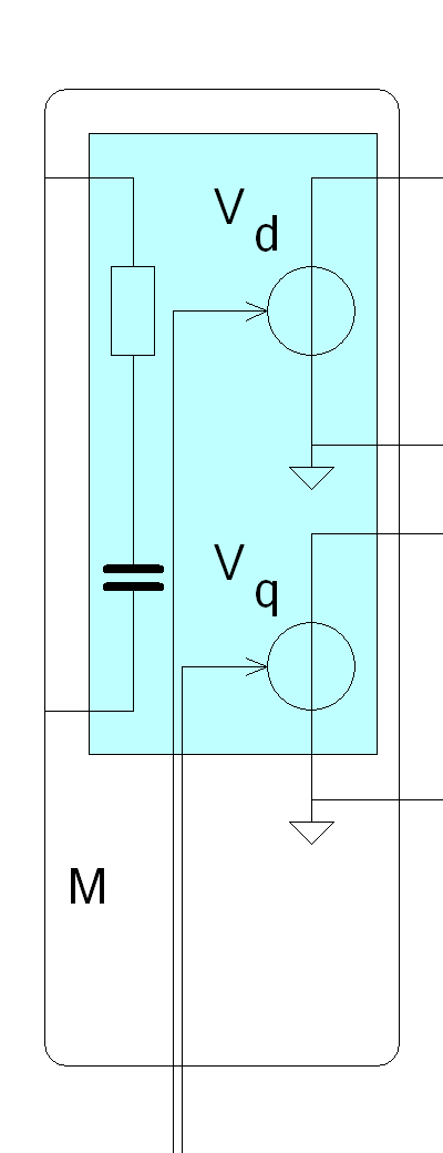
Connection Diagram:
| P | T | ||
| DC |
| D | |
| DGND | |||
| Q | |||
| GND | |||
| QGND | |||
| MODEL | |||
| DQ | |||
| Connections(21) | Position | Remark |
| T | Top | Temperature |
| QGND | Right | |
| Q | Right | |
| P | Top | Losses of the inverter |
| MODEL | Left | Connect Mname for specifying IGBT component name |
| GND | Left | |
| DQ | Bottom | |
| DGND | Right | |
| DC | Left | |
| D | Right |
| Parameters(20) | Default | Remark |
| Vd125 | 0.5 | |
| Rd125 | 10m | |
| Rce125 | 25m | |
| Fs | 20kHz | Switching Frequency [Hz] |
| Inom | 100 | |
| Vnom | 600 | |
| Err125 | 50m | |
| Eon125 | 50m | |
| Eoff125 | 50m | |
| VCE125 | 1 | |
| Err25 | 50m | |
| Eon25 | 50m | |
| Rd25 | 10m | |
| Eoff25 | 50m | |
| Vd25 | 0.5 | |
| Rce25 | 25m | |
| VCE25 | 1 | |
| InitialCdcVoltage | 600 | Initial voltage of the DC link capacitor [V] |
| Cdc | 100uF | Capacitance of the DC link capacitor [Farad] |
| Resr | 10m | Equivalent series resistance of the DC link capacitor [Ohm] |
| Function | IGBT DQ inverter system model with loss calculation. The IGBT switches are replaced by an averaged model. Therefore the simulation speed is high compared to the model with the IGBT switches | |
| Note | This model can not be used to regenerate energy from the three pahse terminals via the diodes to the DC link, since the diodes are not present in the model. | |
| Status | Standard | |
| Select from | Components\Library\PowerConverters\Inverters3phase | |
See also
BlankingTime, BrushlessGatePWM, BrushlessHall2SixPulse, BrushlessPosition2SixPulse, Inverter, InverterIGBTaveraged, Inverter_Averaged, Inverter_IGBT, Inverter_IGBT_Level1, INVERTER_MOSFET, pwm3, PWM_Converter6, PWM_ConverterSymCarrier, PWM_symmetrical, SixPulseAngleControlled, SixPulseAngleControlled120Degr, SixPulseFrequencyControlled, SixStep, SoftStartControl, Softstarter, SVM, VF, VSI_GTO, VSI_PWM,