


AC3 - Current Sensor three phase
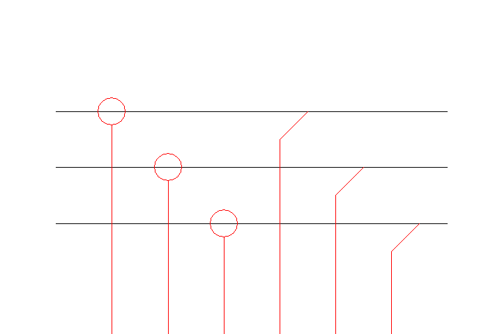
Connection Diagram:
| L1IN |
| L1OUT | |||||
| L2IN | L2OUT | ||||||
| L3IN | L3OUT | ||||||
| I1 | I2 | I3 | V1 | V2 | V3 | ||
| Connections(12) | Position | Remark |
| V3 | Bottom | |
| V2 | Bottom | |
| V1 | Bottom | |
| L3OUT | Right | Negative Sensor terminal L3 |
| L3IN | Left | Positive Sensor terminal L3 |
| L2OUT | Right | Negative Sensor terminal L2 |
| L2IN | Left | Positive Sensor terminal L2 |
| L1OUT | Right | Negative Sensor terminal L1 |
| L1IN | Left | Positive Sensor terminal L1 |
| I3 | Bottom | Current in phase 3 |
| I2 | Bottom | Current in phase 2 |
| I1 | Bottom | Current in phase 1 |
| Parameters(1) | Default | Remark |
| R | 1u | Series resistance of the current sensor |
| Function | This current sensor has only a series resistance. | |
| Status | Standard | |
| Select from | Components\Library\PowerConverters\InverterControl\Sensor | |
See also
I3,