


WRIG - Wound Rotor Induction Generator
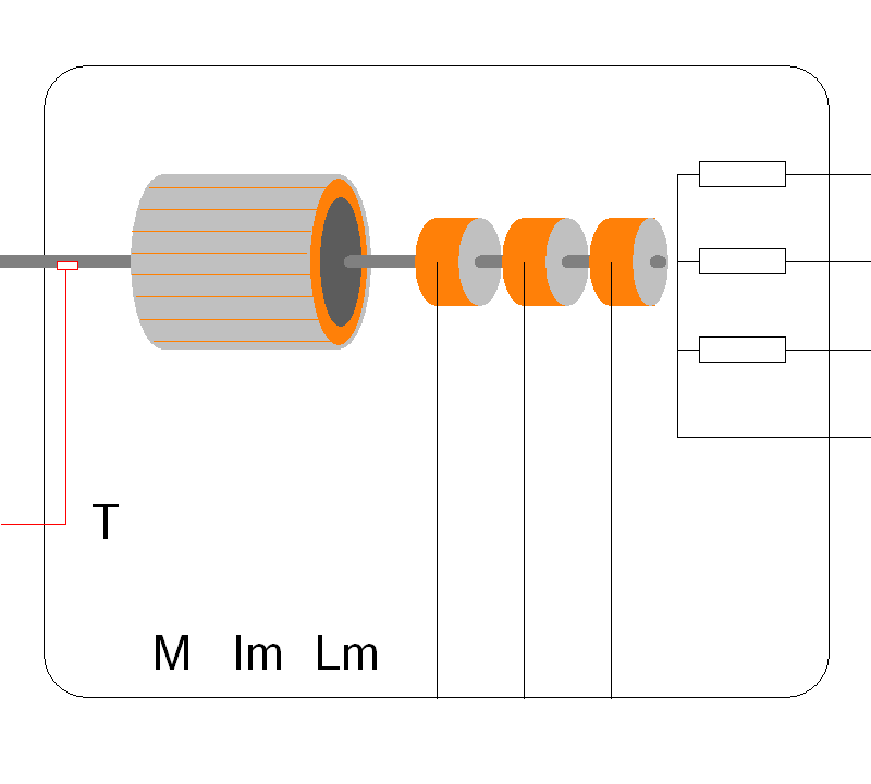
Connection Diagram:
|
| L1 | |||||||
| SHAFT | L2 | |||||||
| L3 | ||||||||
| TORQUE | ||||||||
| AM | IM | LM | R1 | R2 | R3 | |||
| Connections(17) | Position | Remark |
| TORQUE | Left | |
| SHAFT | Left | |
| R3 | Bottom | |
| R2 | Bottom | |
| R1 | Bottom | |
| LM | Bottom | |
| L3 | Right | |
| L2 | Right | |
| L1 | Right | |
| IM | Bottom | |
| AM | Bottom |
| Parameters(9) | Default | Remark |
| Lm | 10m | Stator Magnetizing Inductance |
| p | 4 | pole pairs |
| Lr=Lr'/N^2 | 300u | Rotor leakage inductance in the rotor reference frame |
| Ls | 100u | Stator leakage inductance |
| J | 250 | Rotor Inertia |
| f | 1u | Friction of the rotor |
| Rr=Rr'/N^2 | 5m | Rotor resistance in the rotor reference frame |
| Rs | 1m | Stator resistance |
| WindingRatio=Ns/Nr | 0.25 | Ratio between the number of stator and rotor windings N=Nstator/Nrotor |
| Function | Induction machine model based on the stator fixed coordinate system. The rotor terminals are accessible on the left. | |
| Special | Both the stator and rotor windings are in wye configuration. The rotor leakage inductance Lr and the rotor resistance are now in the rotor reference frame. | |
| Note | The rotor terminals always have to be connected to a three-phase circuit. Default parameters are fora 2.75 MW wind turbine generator | |
| Status | Standard | |
| Select from | Components\Library\ElectricalMachines\IMgenerator | |
See also