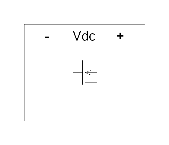
VSI_PWM_DC - Inverter IGBT Thermal System

Connection Diagram:
| AGND | DC | ||||
| ZA | 
| U | |||
| ZB | V | ||||
| ZC | W | ||||
| Connections(10) | Position | Remark |
| ZC | Left | |
| ZB | Left | |
| ZA | Left | |
| W | Right | |
| V | Right | |
| U | Right | |
| DC | Top | |
| AGND | Top |
| Parameters(0) | Default | Remark |
| Function | IGBT inverter system model with loss calculation. The IGBT switches are replaced by an averaged model. Therefore the simulation speed is large compared to the model with the IGBT switches | |
| Note | This model can not be used to regenerate energy from the three pahse terminals via the diodes to the DC link, since the diodes are not present in the model. | |
| Status | Standard | |
| Select from | Components\Library\PowerConverters\Averaged | |
See also
BoostAveraged, BuckAveraged, CCM, ccm_dcm, ccm_dcm_c, csi, CurrentAmplifier, CurrentControl, PIcontrol, ReferenceVoltage, vsi, VSI_PWM, VSI_VF, VSI_VF_control,


