

Inductive Cooking
Induction cooking is a promising technique for all users who value sustainability in kitchens, hotels and restaurants. It is clearly the better alternative to conventional electric stoves or the cost and CO2 emissions of gas stoves. The recent improvements and the associated cost reductions make this technology more and more interesting for private households as well. The text describes how modern induction cookers work.
How does an induction cooker work?
In induction cooking, the heat is generated directly in the cookware. This is done by electromagnetic induction and the resulting generation of eddy currents. In this handson we will look at simulations for a singe ended and a half-bridge induction cooker system with a power of 3.5 kW.
Although the underlying technique has been around for about 100 years, inductive cooking have only attracted increased attention for several years. Meanwhile, induction hotplates are quite popular in the private and commercial sectors. In the field of cooking, they are considered one of the key technological innovations.
A safe technique
Induction cooking is a variant of electric cooking in which the cookware is heated by means of magnetic coils. The elegant thing about this technique is that the cooking surface stays cool, as the heat is generated directly in the cookware. Therefore, compared to other conventional methods, induction cooking is fast and extremely energy efficient - apart from the fact that it does not need an open flame and therefore is safer.
In induction cooking, the heat is generated directly in the cookware, by electromagnetic induction and the resulting generation of eddy currents. The principle of electromagnetic induction was discovered in 1831 by Michael Faraday. It is the phenomenon that an electric current is generated in one circuit when a changing current flows in a neighbouring circuit.
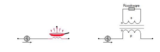
In induction cooking, ferromagnetic cookware is placed on the ceramic or glass cooking surface. Under the cooking surface there is a resonance coil (Figure 1). The induction hotplate and the cookware thereon are in principle nothing more than a transformer in which the cookware plays the role of a shorted secondary coil (load). An alternating current is sent through the resonance coil, creating an oscillating magnetic field, which in turn generates electrical currents in the cookware.
Induction hotplates work exclusively with cookware made of materials that have very specific properties. In order to be heated by the magnetic field, the pot used must be made of a ferromagnetic material such as stainless steel or iron.
No energy consumption without cookware
An induction cooker only consumes energy when there is cookware on it. Unlike a gas flame or a conventional electric cooker, an induction cooker plate can not generate heat on its own. If an induction cooker top is on when there is no cookware on it, or if it remains on after removing the pan, it is as if there is no load on the resonant coil, and accordingly, there is no energy transfer. With no cookware attached, an induction cooker top will go into sleep mode, receiving only a small standby power of less than one watt.
Control
Simply put, an induction cooking element (gas stove would call it a "burner") is the special form of a transformer. When an article of magnetically conductive material, such as a cast iron pan, is placed in the magnetic field generated by the cooking element, energy is transferred ("induced") and the pan or pot is heated. The cooking element represents, so to speak, the primary part and the cookware, the secondary part of a transformer.
By controlling the intensity of the magnetic field, the heat generated in the cooking pot can be controlled. Similar to cooking with gas, the increase or reduction of the energy supply takes place immediately. Induction cooking has several advantages over cooking with conventional electric stoves:
- Time required:
The heat supply to the food is very direct, because the heat is generated evenly in the wall of the pot and not only transmitted from the ground as in gas or electric stoves. - Safety:
There is no open flame as with gas and the hob remains cooler than conventional electric stoves because it is only heated by the heat transferred back from the pot. There is no heating when the hob is on, if there is no pot on it. - Efficiency:
Because the heat is generated directly in the pot, this is about 90%. Comparable values ​​for electric stoves are approx. 60% or 50% when cooking with gas, due to the losses during heat transfer.
Induction cooking is based on the principle of a serial LC resonant circuit, with the coil of the hob representing the inductance L. By changing the switching frequency of the high-voltage half-bridge driver, the current through the coil and thus the intensity of the magnetic field changes. Thus, a control of the transmitted energy and thus the heat to be generated is possible.
Resonant converter technology for induction cooking
Semiconductor devices are used as switching elements in different power converters. In induction cookers these are IGBTs (Insulated Gate Bipolar Transistors). To minimize switching losses, "soft" switching techniques are preferred over "hard" switching solutions (Figure 2). During soft switching, the current or voltage is manipulated in such a way that there is a zero crossing at the moment of switching. Accordingly, these methods are divided into two methods, Zero Voltage Switching (ZVS), that is, switching in voltage zero crossing, and Zero Current Switching (ZCS), switching in current zero crossing.
ZVS and ZCS have their specific advantages and disadvantages and are suitable for different applications. A zero crossing of the current or voltage in the switched circuit can be achieved by resonance in an LC circuit. Transducers of this type are referred to as resonant converter. For induction hotplates mainly two resonant converter topologies are used:
- Quasi-resonant converter
- Half-bridge resonant converter

Driving algorithms of an induction cooker
An induction hotplate thus works according to the principle of an LC resonant converter. The resonance frequency depends not only on the resonant circuit, but also on the size and material of the cookware, so that the resonant frequency changes accordingly. In order to control the power transmitted to the cookware, the input-side mains voltage and the current flow in the IGBT are monitored by a microcontroller and the switching frequency is adjusted accordingly.
Based on the quasi-resonance topology
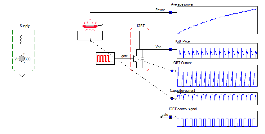
An induction hotplate system based on the quasi-resonant topology with a power of 5 kW was equipped with a IGBT capable of withstanding 1250 V and 100 A. The system is equipped with comprehensive security mechanisms to handle spikes and unsuitable cookware. Figure 2 shows a schematic of the system. Here the resonant circuit consists of the model of the coil with cookware in parallel with a capacitor. The IGBT is pulsed such, that a resonant current oscillates in the pan. The filters and series inductance of the mains grid are modeled by a single inductor in series with a constant supply voltage of 300volts.
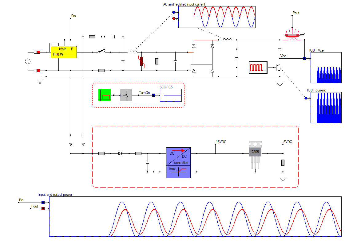
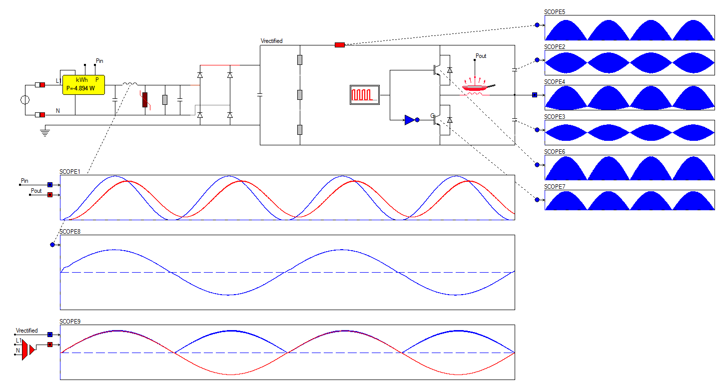
Supplying such a topology form the AC mains requires rectification of the AC mains voltage. Also protection is modeled in the form of an MOV [Metal Oxide Varistor] to protect the system from overvoltage and voltage spikes form the grid. As the load behaves more or less resistive, also the power consumption is sinusoidal according to the AC mains grid frequency. The schematic is extended with the models for the auxiliary power supply for the control circuits.
Based on the half-bridge topology
Applying the half-bridge topology reduces the voltage stress on the switching IGBT's. The voltage over the IGBT's is now clamped by the input voltage and will, apart from parasitic components, not exceed the input voltage.
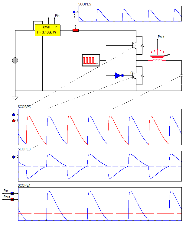
An 3.5 kW, half-bridge induction cooker system was fitted with high-voltage, 650V/40A IGBT and two capacitors. Figure 6 shows the block diagram of this system. The input mains is rectified and filtered and contains a MOV for overvoltage protection. The AC mains connection is modeled with series impedance. Because the cookware mainly behaves like a resistive load, we can clearly see that the power delivered to the cookware is following the amplitude of the AC mains voltage.
Dimensioning the power electronics with gate drivers
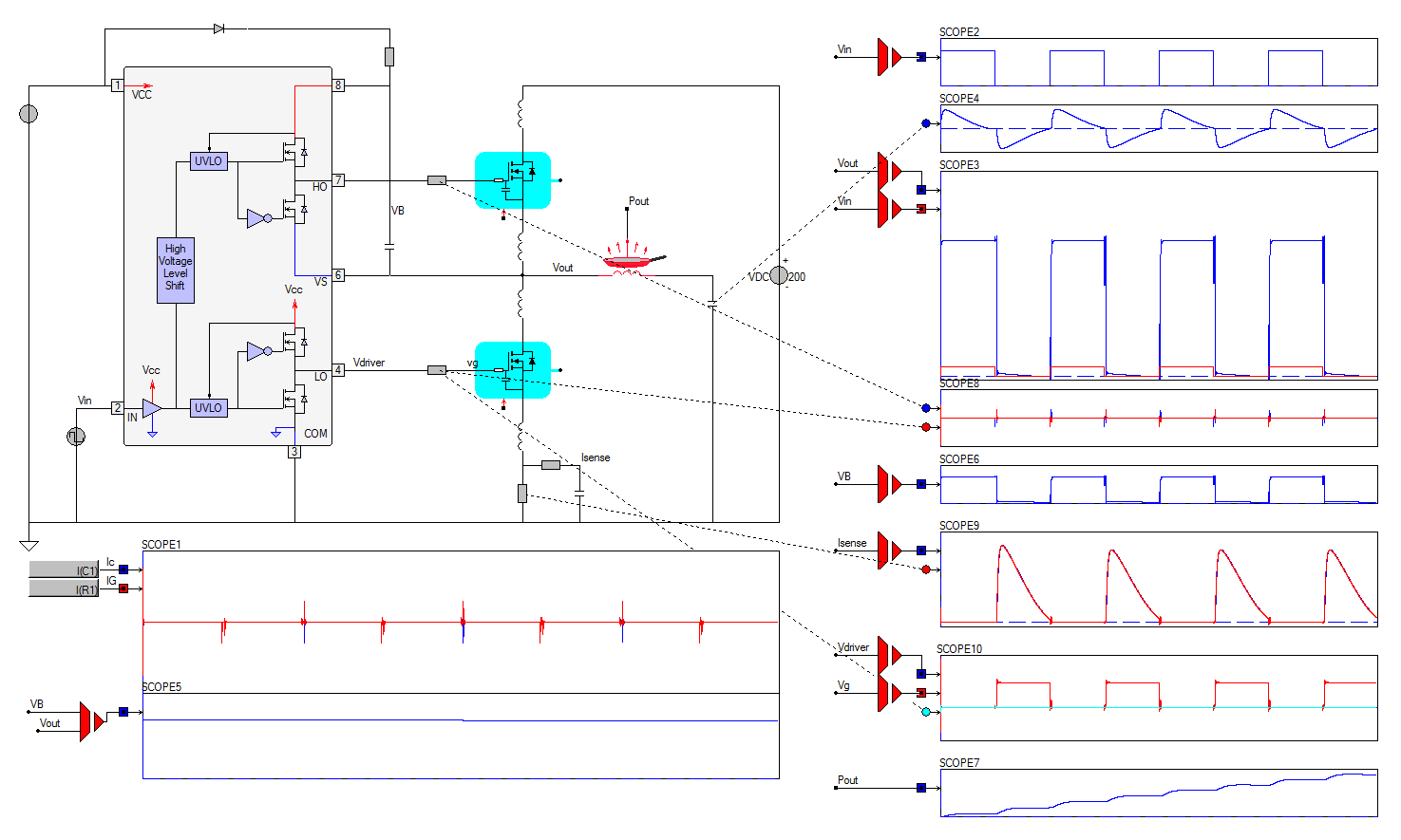
Finally it has got to be designed and implemented and that is where the parasitic components are influencing the waveforms. The schematic below shows half-bridge with 2 Mosfets and a standard gate driver based on the IR2111. The wiring and pcb inductance between the the two Mosfets is accounted for with 50nH parasitic inductances at the Drain and Source connections of the Mosfets. The gate driver is modeled in detail including all delays and blanking time. The bootstrap circuit for feeding the high side mosfet driver is included in this simulation.